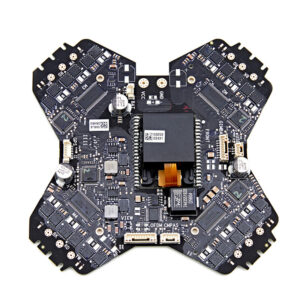
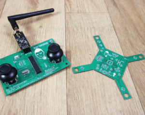
Despite the increasing level of semiconductor integration, ready-to-use systems-on-chip for many applications, and the increasing availability of many powerful out-of-the-box development boards, the application of electronics in many use cases A custom Unmanned Drone PCB Board Copying still needs to be used.

Copia de placas de circuito impreso de drones no tripulados
In a one-off development, even an ordinary Unmanned Drone PCB Board can play a very important role. The Unmanned Drone PCB Board is the physical platform for design and the most flexible part for electronic system design from raw components. This article will introduce several golden rules of Unmanned Drone PCB Board Copying, most of which have not changed since the birth of commercial PCB design 25 years ago, and are widely applicable to various high speed PCB board design copying projects, whether it is for young electronic design engineers or more mature engineers. Circuit board manufacturers have a great guiding role.

Unmanned Drone PCB Board Copying
The following content of this article introduces the ten most effective reverse engineering unmanned drone pcb board rules that electronic design engineers should keep in mind and practice when using design software for PCB layout design and commercial manufacturing. Engineers don’t need to implement these laws in chronological order or relative importance, simply following them all can dramatically change product design;

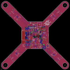
reverse engineering unmanned drone pcb board schematic diagram and gerber file
Set and always use the grid spacing that fits the most components. Although multi-grid seems to be effective, if engineers can think more in the early stage of electronic drone PCB layout design cloning, they can avoid difficulties in spacing settings and maximize the use of circuit boards. Since many devices are available in a variety of package sizes, engineers should use the product that best suits their design. Additionally, polygons are critical to board copper pours, and multi-grid boards typically have polygon fill deviations when applying polygon copper pours, which, while not as standard as single-grid based, can provide board life beyond what is required


