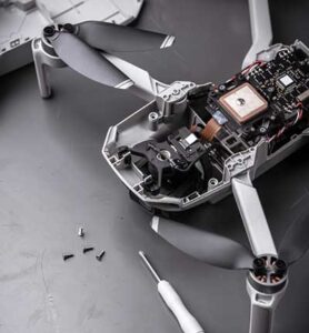
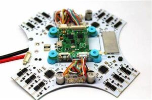
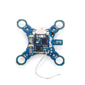
Unmanned Aerial Vehicle PCB Board Copying sounds trivial, but it should be kept in mind at every stage, even if it means changing the Unmanned Aerial Vehicle PCB Board layout to optimize trace lengths. This also applies especially to analog and high-speed digital circuits where system performance is always partially limited by impedance and parasitic effects;

Unmanned Aerial Vehicle PCB Board Copying
Power plane copper is the quickest and easiest option for most printed wiring board reverse engineering design software. By sharing a large number of wires, current flow is guaranteed at the highest efficiency with minimal impedance or voltage drop, while providing an adequate return path to ground.
If possible, multiple power supply lines can also be run in the same area of the Unmanned Aerial Vehicle PCB Board to confirm whether the ground plane covers most of a certain layer of the PCB, which is conducive to the interaction between the running lines on adjacent layers;

Copia de placas de circuito impreso de vehículos aéreos no tripulados
For example: placing the discrete components required for the OpAmp operational amplifier close to the device so that the bypass capacitors and resistors can cooperate with it, this helps to optimize the routing length mentioned in the second rule, and also makes the test and fault detection easier;

Unmanned Aerial Vehicle PCB Board reverse engineering for its gerber file, schematic diagram and layout drawing, BOM List
Choosing the size that best fits the equipment used by the manufacturer can help reduce prototyping and manufacturing costs. Do the Unmanned Aerial Vehicle PCB Board Copying on the panels first, contact the pc board manufacturer to get their preferred size specifications for each panel, then revise your design specifications and try to repeat your design as many times as possible within those panel sizes


