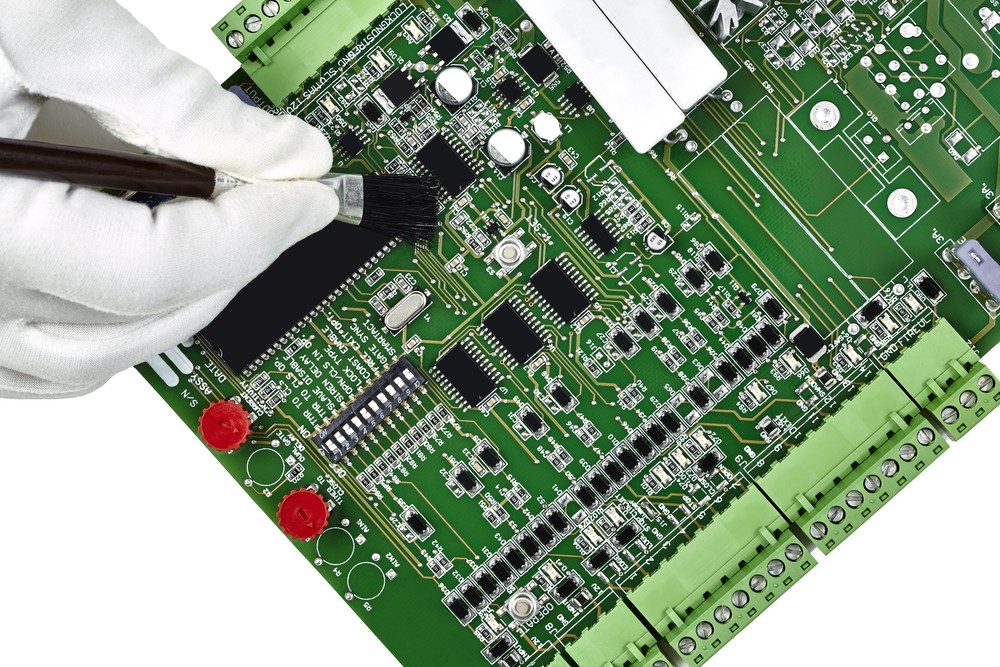
Toshiba Hemodialysis Circuit Board Maintenance process and principle analysis: Check that there is no obvious burnout on the circuit board, restart the machine, the phenomenon is still the same. Clean it with a brush, absolute alcohol, etc., and check that there is no obvious abnormality in the joints. Turn on again. It is measured that the other reference voltages are within the normal range except + -300mV (TP49, 51) voltage, and the two comparative TP50 voltage 5.19V is normal, and the trial potentiometer P21 can be seen to slightly increase the two voltages, but the maximum is only about 3.5V, which will cause the shut down of hemodialysis machine motherboard.

After removing the circuit board, there are scorch marks under the resistors R213 and R207 that are close together. The measured resistance is normal but the two resistors are still replaced. The phenomenon is still the same after the replacement. According to the circuit board schematic diagram acquired by reverse engineering PCB board, the lOMft large resistance R220, R222, R208, capacitor C129, etc. are regarded as an open circuit, and the TP51 DC equivalent circuit diagram to ground is drawn, Considering the low voltage across the resistor R216 or the series voltage-dividing resistor P21 + R215 + R214, then the two TP51 values will be reduced accordingly (it can be seen from the circuit diagram that TP49-synchronously reduced, so only need to analyze TP51).
Measure the resistance in sequence. The measured value of P21is 2 Kft within the normal range, and the resistance values of all the resistors except R216 are normal. The nominal value of R216 is 7.8K11, and the measured value is 5. 6Kn. Check that the appearance is normal. The resistance measured after soldering a foot is normal. The measured resistance between empty pads is 20Kft. The actual measurement and equivalent circuit diagram analysis > 20Kfi, indicating that there is a local short circuit.


