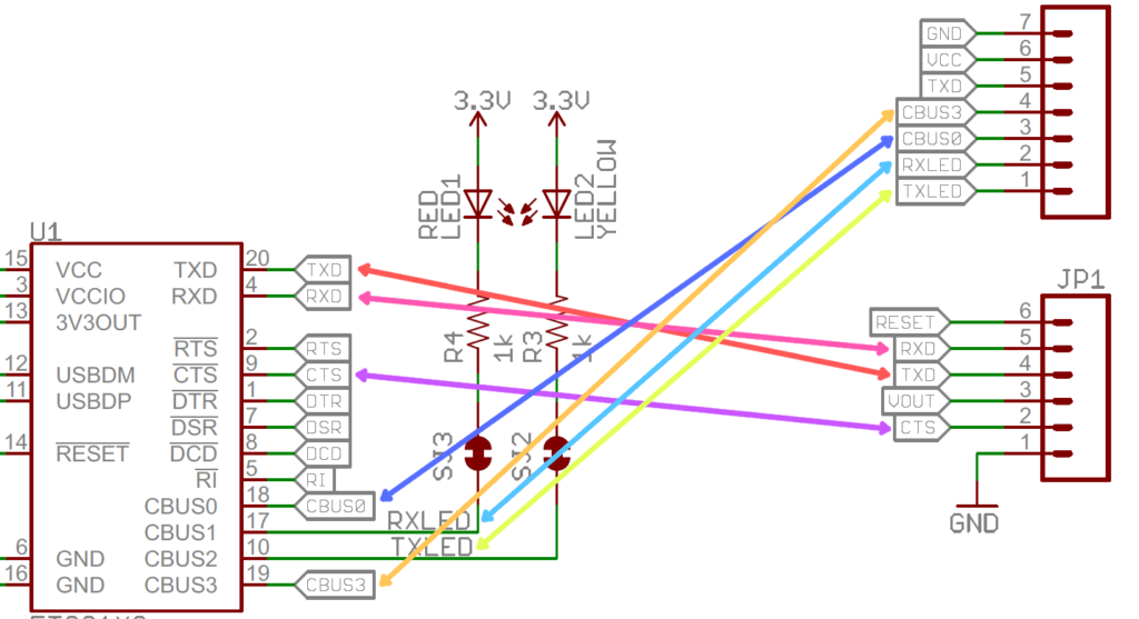
Text Symbol of PCB Schematic Diagram are an important part of the circuit diagram especially when redesign PCB board. In order to further emphasize the nature of the graphical symbols, and also to analyze, understand and explain the convenience of the circuit diagram, the text symbols of the components are marked next to the graphic symbols of the respective components. For example, “R” denotes a resistor, “C” denotes a capacitor, “L” denotes an inductor, “VT” denotes a transistor, and “IC” denotes an integrated circuit or the like.
In addition to specifying uniform graphical symbols and text symbols, the schematic diagram also follows certain drawing rules. Understanding and mastering the general drawing rules of PCB Schematic diagrams is essential for understanding it.
A. Signal processing flow direction of the Schematic diagram
The direction of the signal processing flow in the circuit diagram is generally from left to right, and the unit circuits that process the signals successively are arranged in a left-to-right direction, which is the most common arrangement.

B. Connecting wires
The connecting wires between the components are indicated by solid lines in the PCB Schematic diagram. The connection and intersection of the wires are drawn with a dot indicating that the two wires are connected together. There is no dot at the intersection, indicating that the two wires cross and are not connected. A cross-page connection usually has a name and a number next to it indicating where it is connected.


