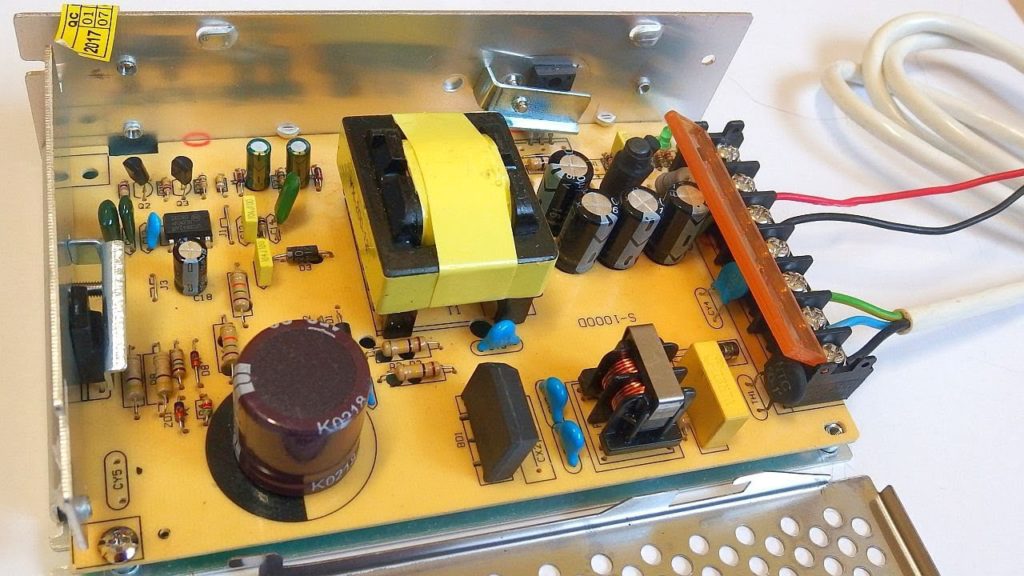
In any Switching Power Supply PCB Board Cloning, the physical design of the PCB is the last link. If the cloning method is not correct, the PCB may radiate excessive electromagnetic interference, resulting in unstable power supply. As a designer, you must understand the physical workings of the circuit and design a high quality switching Power supply PCB board.

The switching power supply contains high-frequency signals. Any printed circuitry on the PCB board can function as an antenna. The length and width of the printed circuitry will affect its impedance and inductance, thus affecting the frequency response. Even a printed line that passes a DC signal can couple to an RF signal from an adjacent printed line and cause a circuit problem (even radiating an interference signal again).
Therefore, all traces through alternating current should be designed to be as short and wide as possible, which means that all components connected to the trace and connected to other power lines must be placed in close proximity. The length of the trace is proportional to the inductance and impedance it exhibits, and the width is inversely proportional to the inductance and impedance of the trace. The length reflects the wavelength of the response of the printed line obtained from COPY PRINTED CIRCUIT BOARD GERBER FILE. The longer the length, the lower the frequency at which the printed line can transmit and receive electromagnetic waves, and it radiates more RF energy in the process of Switching Power Supply PCB Board Cloning.
Choosing the right MOSFET for the cloning of the switching power supply pcb board or synchronous rectification function can also help reduce electromagnetic interference. When the MOSFET device is powered down, the low voltage/current (like the FDS6690A) can reduce spike interference.


