LVDS Logic in Switch Panel Circuit Board Reverse Engineering
Recently, LVDS logic in Switch panel circuit board reverse engineering (low-voltage-differential-signaling) has attained widespread popularity because of similar characteristics, but with lower amplitudes and lower power dissipation than ECL. The defining LVDS specification can be found in the References.
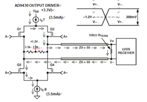
The LVDS logic swing is typically 350 mV peak-to-peak centered about a common-mode voltage of +1.2 V. A typical driver and receiver configuration is shown in Figure 12.47. The driver consists of a nominal 3.5 mA current source with polarity switching provided by PMOS and NMOS transistors as in the case of the AD9430 12-bit, 170-MSPS/210-MSPS ADC. The output voltage of the driver is nominally 350 mV peak-to-peak at each output, and can vary between 247 mV and 454 mV.
The output current can vary between 2.47 mA and 4.54 mA. The LVDS receiver is terminated in a 100 Ù line-to-line. According to the LVDS specification, the receiver must respond to signals as small as 100 mV, over a common-mode voltage range of 50 mV to +2.35 V. The wide common-mode receiver voltage range is to accommodate ground voltage differences up to ±1 V between the driver and receiver.

LVDS Driver and Receiver
The LVDS edge speed is defined as the 20% to 90% rise/fall time (as opposed to 10% to 90% for CMOS logic) and specified to be less than < 0.3 tui, where tui is the inverse of the data signaling rate. For a 210 MSPS sampling rate, tui = 4.76 ns, and the 20% to 80% rise/fall time must be less than 0.3 × 4.76 = 1.43 ns. For the AD9430, the rise/fall time is nominally 0.5 ns.


