Set Double Side PCB Layout Wiring Reverse Engineering Constraints firstly must report design parameters, after the PCB layout design is basically determined.

Set Double Side PCB Layout Wiring Reverse Engineering Constraints firstly must report design parameters, after the PCB layout design is basically determined
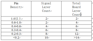
The statistical function of the PCB design reverse engineering tool is used to report basic parameters such as the number of networks, network density, and average pin density to determine the number of PCB wiring card signal layers required.
The determination of the number of signal layers can refer to the following empirical data

The determination of the number of signal layers can refer to the following empirical data
Note: PIN density is defined as: board area (square inch)/(total number of pins on board/
14) The specific determination of the number of wiring layers should also consider factors such as the reliability requirements of the single board, the working speed of the signal, the manufacturing cost and the delivery time.
1. Wiring layer settings In the design of high-speed digital circuits, the power supply and the ground should be as close together as possible, and no wiring should be arranged in the middle.
All wiring layers are as close as possible to a plane layer, and the ground plane is preferably a wiring isolation layer. In order to reduce the electromagnetic interference of signals between layers, the signal lines of adjacent wiring layers should be in a vertical direction.
You can design 1-2 impedance control layers according to your needs. If you need more impedance control layers, you need to negotiate with the PCB manufacturer. The impedance control layer should be clearly marked as required.
Distribute the network wiring required for impedance control on the board on the impedance control layer.


