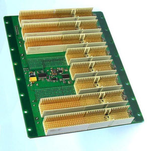
Accompany with the DATA-BUS being organized into the tight trace by tissue on the first layer, designer start to plan the detail #3 to the 3rd layer’s conversion. And considering the matching distance of the Server Backplane Board, please notice, this topology route on the 3rd layer must be wider than the top layer, and by taking the required extra space for adaptive resistance into account, besides, through Server Backplane Board Reverse Engineering, designer can regulate the exact position of the layer switch;

Server Backplane Board reverse engineering
When the topology route go alongside the drawings to the #4 detail, need to lead out a lot of bit T type conjunction points on various components’ lead. Designer will normally choose to keep most of these connections on the layer 3, and go through other layers for the purpose of component pin-out connection. As a result of that, they draw a topology area to indicate the data-bus strip on the 4th layer’s connection, while making these single T style bits to the 2nd layer. And then use other through hole to connect to component’s lead.
Topology route can go alongside the 3rd layer until it reaches the 5th details to connect the power supply component. These connections on the layout drawing acquired from server backplane board Reverse Engineering can go from the power supply lead to the scroll down resistor of the power supply components. Designer use another topology area to regulate the connection from layer 1 to layer 3, in there the lead of components are all belongs to the power supply components and scroll down resistors.


