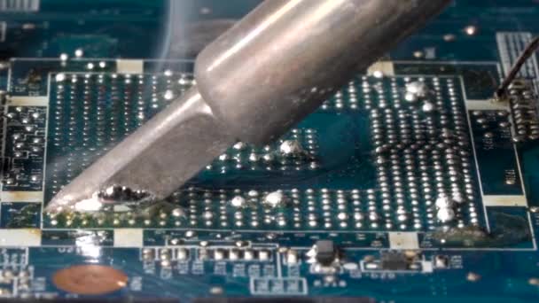
Reverse Engineering SMT RF PCB Board to improve electronic component’s layout drawing, since SMT generally uses infrared furnace reflow soldering to achieve the welding of components, the layout of the components affects the quality of the solder joints, which in turn affects the yield of the product. For SMT RF circuit board reverse engineering, electromagnetic compatibility requires each Circuit modules do not generate electromagnetic radiation as much as possible.

And it has a certain ability to resist electromagnetic interference. Therefore, the layout of power components in the PCB card also directly affects the interference and anti-interference ability of the circuit itself, which is also directly related to the performance of the designed circuit. Considering the layout of ordinary RF PCB layout design and reverse engineering,
Mainly also need to consider how to reduce the mutual interference between the various parts of the RF circuit, how to reduce the interference of the circuit itself to other circuits and the anti-interference ability of the circuit itself.
According to experience, the quality of the RF circuit depends not only on the performance indicators of the RF circuit board itself, but also on the interaction with the CPU processing board. Therefore, when designing printed circuit board, a reasonable layout is particularly important


