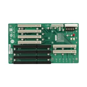
The detail plan of this level consume only 30 seconds to complete the task, once this plan has been obtained, the engineer will probably want to Reverse Engineering PCIE Backplane Gerber File or create the topology plan for next layer immediately, and then use automatically layout to finish all of the topology plan.

Reverse Engineering PCIE Backplane Gerber File
From the completion of planning of the result of automatically layout will take no longer than 10 seconds, in fact this speed is not important, in fact if the intention of designer who Reverse Engineering PCIE Backplane Gerber File has been neglected, which will consequently lead to the bad result of automatically layout, the whole process will be viewed as a waste of time.
All of the pins coming out from the component lead should be in line with the expression of designer which normally locate on the first layer and will be compressed to intense data-bus structure, the conversion among first and third layer will happen on the detail number 3, which apply the through-hole format to occupy great space.
And there is thing need to reiterate is the impedance effect must be taken into consideration, as a result of that, the track can be wider, and greater space just as the real track space.
Due to the requirement of through-hole must fit for the single bit T type joint point with enlarged topology route. This plan can once again express the intension of designer against those single bit T shape exchange point, from the third layer layout to the forth layer, besides, the third layer’s track mark is closely approached to each other even though these through hole can be expanded but these holes will be closely tight soon after heating up.


