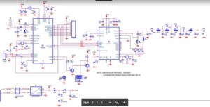
Reverse Engineering PCB Board Signal Tracks Pattern is also a critical task for printed circuit board layout design cloning;
The signal lines on the circuit board (including digital and analog circuits) should be as short as possible. This basic criterion will reduce the possibility of extraneous signals coupling into the signal path.

Reverse Engineering PCB Board Signal Tracks Pattern
Pay special attention to the input terminals of analog devices, which usually have higher impedance than output pins or power pins.
For example, the reference voltage input pin of the A/D converter is the most sensitive during conversion. For the 12-bit converter in Figure 1, the input pins (IN+ and IN-) are also sensitive to the noise introduced. The input end of the op amp may also introduce noise into the signal path.
These terminals usually have an input impedance of 109W to 1013W.


