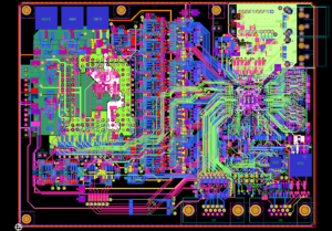
Six things to consider when Reverse Engineering PCB Board Schematic from Layout Design. All the examples mentioned were developed using the Multisim design environment, but the same concepts apply when using different EDA tools.
Initial PCB Board schematic diagram restoration:
In the process of reverse engineering the schematic from the layout environment through the net-list file, device information, netlist, layout information and initial trace width settings will also be transferred.

Reverse Engineering PCB Board Schematic from Layout Design
Here are some recommended steps for the layout design stage:
1. Set the grid and unit to appropriate values. In order to achieve finer layout control of components and traces, the device grid, copper-clad grid, via grid and SMD grid can be designed to be 1mil.
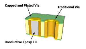
2. Set the blank area and vias of the circuit board outer frame to the required values. PCB manufacturers may have specific minimum or nominal recommended values for blind and buried via settings of pcb board layout file cloning.

nominal recommended values for blind and buried via settings of pcb board layout file cloning.
3. Set the corresponding pad/via parameters according to the ability of the PCB manufacturer. Most PCB manufacturers can support smaller vias with a bore diameter of 10 mils and a pad diameter of 20 mils.
4. Set design rules according to requirements.
5. Set up customized shortcut keys for commonly used layers so that you can quickly switch layers (and create vias) during routing.


