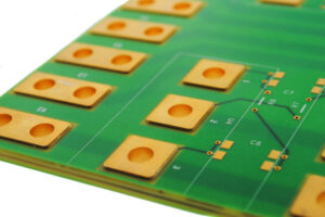
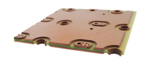
To figure out how to increase the over-current capability of the PCB circuit board, Reverse Engineering PCB Board Layout Circuitry scheme will do.
Take a double-layer PCB board reverse engineering as an example. This kind of circuit board usually has a three-layer structure: copper foil, substrate plate, and copper foil. The copper foil is the path through which the current and signal in the printed circuit board pass.

Reverse Engineering PCB Board Layout Circuitry to increase overcurrent capability
According to the knowledge of middle school physics, we can know that the resistance of an object is related to the material, cross-sectional area, and length. Since our current runs on the copper foil, the resistivity is fixed. The cross-sectional area can be regarded as the thickness of the copper foil, which is the copper thickness in the PCB reverse engineering processing options.

the resistivity is fixed. The cross-sectional area can be regarded as the thickness of the copper foil, which is the copper thickness in the PCB reverse engineering processing options
Usually copper thickness is expressed in OZ, the copper thickness of 1 OZ is 35 um, 2 OZ is 70 um, and so on. Then it can be easily concluded that when a large current is to be passed on the PCB, the wiring should be short and thick, and the thicker the copper thickness of the PCB, the better.
Actually, in engineering, there is no strict standard for the length of pcb wiring circuitry pattern. Usually used in engineering: copper thickness / temperature rise / wire diameter, these three indicators to measure the current carrying capacity of the PCB board.


