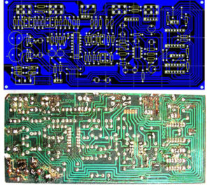
When Reverse Engineering PCB Board Gerber File it is important to keep below points in mind to avoid any unexpected discrepency or interruption happens:
1. Have a reasonable direction: such as input / output, AC / DC, strong / weak signal, high frequency / low frequency, high pressure / low voltage, etc., their direction should be linear (or separated), not mutually blend. Its purpose is to prevent mutual interference. The best direction is in a straight line, but it is generally difficult to achieve. The most unfavorable trend is the ring. Fortunately, isolation can be improved. For DC, small signal, low voltage requirements can be lower when Reverse Engineering PCB Board Gerber File. So “reasonable” is relative.

Reverse Engineering PCB Board Gerber File Precaution
2. Choose a good grounding point: a small grounding point I don’t know how many engineers and technicians have done much about it, which shows its importance. In general, it is required to share a common ground, for example, multiple ground wires of the forward amplifier should be connected and then connected to the trunk line, etc. In reality, it is difficult to do it completely because of various restrictions, but you should try to follow it. This problem is quite flexible in practice. Everyone has their own set of solutions. It can be easily understood if it can be explained for a specific board.
3. Reasonably arrange power supply filtering/decoupling capacitors: Generally, only a few power supply filtering/decoupling capacitors are drawn in the schematic diagram extracted from Reverse Engineering PCB Board Gerber File, but it is not indicated where they should be connected. In fact, these capacitors are set for switching devices (gates) or other components that require filtering/decoupling. These capacitors should be placed as close as possible to these components, and it would be ineffective if they are too far apart. Interestingly, the grounding point problem is less noticeable when the power supply filtering/decoupling capacitors are properly arranged.


