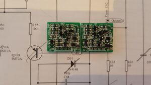
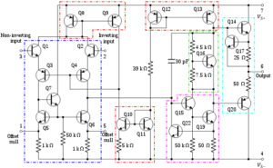
Although a good OP AMP PCB Board Schematic Diagram cannot guarantee a good CIRCUIT BOARD LAYOUT Drawing, a good wiring starts with a good schematic, as a result of that, Reverse Engineering OP AMP PCB Board Schematic Diagram will help to make a better one for electrical engineer in the upcoming progress of OP AMP PCB board manufacturing:

Reverse Engineering OP AMP PCB Board Schematic Diagram
Think carefully when reverse engineer the PCB board schematic, and you must consider the signal flow of the entire circuit. If there is a normal and stable signal flow from left to right in the schematic when clone signal amplifier PCBA, then there should be an equally good signal flow on the PCB.

Think carefully when reverse engineer the PCB board schematic, and you must consider the signal flow of the entire circuit. If there is a normal and stable signal flow from left to right in the schematic when clone signal amplifier PCBA, then there should be an equally good signal flow on the PCB
Give as much useful information as possible on the schematic. Because sometimes the circuit design engineer is not there, the customer will ask us to help solve the circuit problem, the designers, technicians and engineers engaged in this work will be very grateful, including us.
In addition to common reference identifiers, power consumption, and error tolerance, what other information should be given in the schematic? Here are some suggestions to turn ordinary schematics into first-class schematics from Reverse Engineering OP AMP PCB Board.


