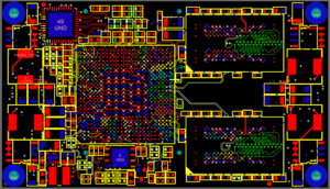
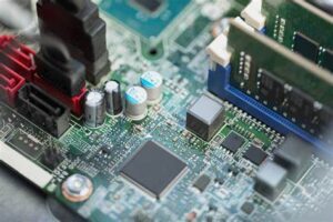
Motherboard is the piece of electronic printed circuit board which can be viewed as the “backbone” of the electronic device/controller unit, or more appropriately as the “basement” that holds all the pieces together, Reverse Engineering Motherboard Layout Design will help us recreate the schematic diagram of this electronic pcb board, for the purpose of troubleshoot motherboard malfunctions and rework it, or re-manufacture electronic PCB card for PCB cloning;

Reverse Engineering Motherboard Layout Design will help us recreate the schematic diagram of this electronic pcb board, for the purpose of troubleshoot motherboard malfunctions and rework it, or re-manufacture electronic PCB card for PCB cloning
Reducing the loop area of motherboard layout design not only reduces the radiation, but also reduces the loop inductance, making the circuit performance better which can be realized through PCB reverse engineering.
Reducing the loop area requires us to accurately design the return path of each trace.
When multiple PCB boards are connected through connectors, it is also necessary to consider minimizing the loop area, especially for large di/dt signals, high frequency signals or sensitive signals. It is best that one signal wire corresponds to one ground wire, and the two wires are as close as possible. If necessary, twisted pair wires can be used for connection (the length of each twisted pair wire corresponds to an integer multiple of the noise half-wavelength).

When multiple PCB boards are connected through connectors, it is also necessary to consider minimizing the loop area, especially for large di/dt signals, high frequency signals or sensitive signals. It is best that one signal wire corresponds to one ground wire, and the two wires are as close as possible.
If you open the computer case, you can see that the USB interface between the motherboard and the front panel is connected with a twisted pair, which shows the importance of twisted pair connection for anti-interference and reducing radiation.
For the data cable, try to arrange more ground wires in the cable, and make these ground wires evenly distributed in the cable, which can effectively reduce the loop area.
Although some inter-board connection lines are low-frequency signals, because these low-frequency signals contain a lot of high-frequency noise (through conduction and radiation), it is easy to radiate these noises if not handled properly.
When reverse engineering motherboard wiring layout, first consider high-current traces and traces that are prone to radiation.
Switching power supplies usually have 4 current loops: input, output, switch, freewheeling. Among them, the input and output current loops are almost direct current, and almost no EMI is generated, but they are easily disturbed; the switch and freewheeling current loops have larger di/dt, which needs attention.


