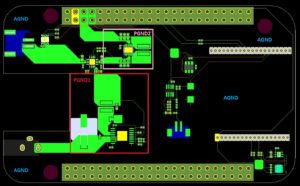
Mixed Signal PCB Reverse Engineering
To further complicate the issue, Reverse Engineering Mixed Signal PCB can find that mixed-signal ICs have both analog and digital ports, and because of this, much confusion has resulted with respect to proper grounding techniques. In addition, some mixed-signal ICs have relatively low digital currents, while others have high digital currents. In many cases, these two types must be treated differently with respect to optimum grounding.
Sigma-delta (-) ADCs also require high speed clocks because of their high oversampling ratios. Even high resolution, so-called “low frequency”- industrial measurement ADCs (having throughputs of 10 Hz to 7.5 kHz) operate on 5-MHz or higher clocks and offer resolution to 24-bits (for example, the Analog Devices AD77xx-series).

reverse engineering mixed signal pcb
Digital and analog design engineers tend to view mixed-signal devices from different perspectives, and the purpose of this section is to develop a general grounding philosophy that will work for most mixed signal devices, without having to know the specific details
of their internal circuits.
From the previous discussion it should be clear that the issue of grounding can not be handled in a “cookbook” approach. Unfortunately we can not give a list of things to do that will guarantee success. We can say that there are certain things that if they aren’t done will probably lead do difficulties.
And, what works in one frequency range may not necessarily work in another frequency range. And, often, there are competing
requirements. The best way to handle grounding is to understand how the currents flow.


