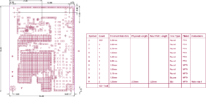
When we are processing Reverse Engineering High Speed Circuit Board Drilling Drawing, the seemingly simple through holes (vias) often bring a large error effect to the redesign of printed circuit board layout. The adverse effects caused by the effect can be tried in the design:
1. From the consideration of cost and signal quality, choose a via of reasonable size. For example, for 6-10 layer memory module PCB layout design, it is better to replace 10/20Mil (drilled/replaced) vias. For some high-density small-size PCB board design, you can also try to use 8/18Mil vias . Under the existing technical conditions, it is difficult to use vias of smaller size. For the vias of the power supply or the ground wire, you can consider using overcoming dimensions to reconstruct the error.
2. The two formulas discussed above can be concluded that using a thinner PCB board is beneficial for aligning the two parasitic parameters of the via.

When we are processing Reverse Engineering High Speed Circuit Board Drilling Drawing, the seemingly simple through holes (vias) often bring a large error effect to the redesign of printed circuit board layout. The adverse effects caused by the effect can be tried in the design
3. The signal traces on the PCB should not change layers as much as possible when reverse engineering electronic PCB board, and try not to use any vias in advance.
4. The power and ground pins should be drilled through the nearest hole. The shorter the lead between the hole and the pin, the better, because they will increase the inductance. .
5. Place some grounded vias near the vias for signal changeover. The gate provides the latest circuit for the signal. You can even place a lot of extra ground vias on the PCB. Of course, the design needs to be flexible. The via model discussed above is the case where each layer overlaps. Sometimes, we can replace or even remove certain layers. Especially in the case of very high via density, it may lead to the formation of a broken groove in the copper layer. To solve this problem, in addition to moving the position of the via, we can also consider placing the via in the copper layer On the alternative size.


