Because most customers use double-sided boards for design, so it is critical to Reverse Engineering Double Side PCB Board Impedance Design when an example is given for the typical 1.6mm, 1.0mm thickness PCB design for two-layer boards:
Case 1: PCB thickness 1.6mm
Considering the influence of PCB board thickness, it is difficult to fully comply with the 3W principle. It is necessary to ensure the 50Ω wiring and ensure that it does not affect the surrounding components. Therefore, it is recommended that customers do not place other components around the antenna and place them on the PCB. Keep the trace as far away as possible from the RF part.
After a lot of actual verification, the following design can ensure that the RF impedance is controlled at about 50Ω, and the impact is minimal:
The RF line width is 43 mils, and the distance from the ground (blue) next to it is 8 mils. The RF line reference layer directly below the RF trace is usually a complete ground (red). Complete ground protection is required around the RF line, and as many ground holes as possible along the routing direction. It is not recommended to have any other traces or devices around the RF trace and its reference ground.

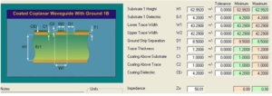
Theoretical calculation of 50Ω impedance in the process of Reverse Engineering Double Side PCB Board Impedance Design
The parameters of Er1, T1, C1, C2 and CEr are generally confirmed by the PCB manufacturer. The craftsmanship and materials of each PCB manufacturer are slightly different, and need to be confirmed with the PCB manufacturer.
H1 is the thickness of the PCB, W1 is the line width, and D1 is the distance from the line to the GND next to it. Errors should be considered in actual production. Case 2: When the PCB thickness is 1.0mm and the PCB thickness is 1.0mm, the RF line width on the PCB is 35mil, and the distance between the line and the GND next to it is 8mil


