When Reverse Engineering Circuit Board Gerber File, you need to use a relatively small power resistor as a sampling resistor to sample large currents. Many times we will use a large package power resistor to do it, such as 2010, 1812, the power is generally 0.5W. But have we thought about using PCB traces to design a sampling resistor?
The following content will describes how to reverse design a 0.05 ohm with PCB traces. First understand the physical knowledge, the resistivity formula of a conductor: R =ρL/S, where ρ is the resistivity of a specific conductor, L is the length of the conductor, and S is the cross-sectional area of the conductor from PCB Board reverse engineering.
It can be known from the above conductor resistivity formula that to design 0.05 ohms with PCB traces, it is necessary to know the resistivity of the PCB conductor, the length of the trace, and the cross-sectional area of the trace.

Reverse Engineering Circuit Board Gerber File, you need to use a relatively small power resistor as a sampling resistor to sample large currents. Many times we will use a large package power resistor to do it,
The PCB conductor material is copper, and the resistance of copper. The resistivity of copper can be found in the table: 1.75×10E-08. The cross-sectional area of the trace can be calculated from the trace width and copper thickness. The PCB copper thickness is 1OZ, 1/2OZ, 1/3OZ, etc.
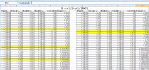
The width and length of the trace cannot be known right away, it needs to be calculated. For the convenience of calculation, we can use the EXCEL table to calculate some values that meet the requirements


