Separate AGND & DGND Through Reverse Engineering Circuit Board
Note also that many ADCs and DACs have separate analog ground (AGND) and digital ground (DGND) pins through Reverse Engineering Circuit Board. On the device data sheets, users are often advised to connect these pins together at the package. This seems to conflict with the advice to connect analog and digital ground at the power supplies, and, in systems with more than one converter, with the advice to join the analog and digital ground at a single point.
There is, in fact, no conflict. The labels “analog ground” and “digital ground” on these pins refer to the internal parts of the converter to which the pins are connected, and not to the system grounds to which they must go. For example, with an ADC, generally these two pins should be joined together and to the analog ground of the system.
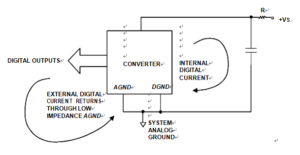
It is not possible to join the two pins within the IC package, because the analog part of the converter cannot tolerate the voltage drop resulting from the digital current flowing in the bond wire to the chip. But they can be so tied, externally. Below Figure illustrates this concept of ground connections for an ADC.
If these pins are connected in this way, the digital noise immunity of the converter is diminished somewhat, by the amount of common-mode noise between the digital and analog system grounds. However, since digital noise immunity is of the order of hundreds or thousands of millivolts, this factor is unlikely to be important.
The analog noise immunity is diminished only by the external digital currents of the converter itself flowing in the analog ground. These currents should be kept quite small, and this can be minimized by ensuring that the converter outputs don’t see heavy loads. A good solution towards this is to use a low input current buffer at the ADC output, such as a CMOS buffer-register IC.
If the logic supply to the converter is isolated with a small resistance and decoupled to analog ground with a local 0.1 µF capacitor, all the fast-edge digital currents of the converter will return to ground through the capacitor, and will not appear in the external ground circuit. If the analog ground impedance is maintained low, as it should be for adequate analog performance, additional noise due to the external digital ground current should rarely present a problem.


