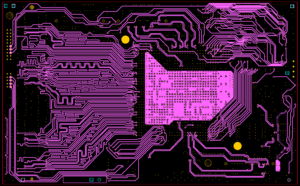
When Reroute Electronic PCB Board Signal Gerber Layer, a direct current return path can be provided under each signal line, so that the loop area formed is small. The use of optical isolation devices or transformers can also achieve the signal across the division gap. For the former, the optical signal is crossed across the division gap; in the case of a transformer, the magnetic field is crossed across the division gap. Another feasible method is to use differential signals: the signal flows in from one line and returns from another signal line. In this case, it is unnecessary to use it as a return path.

Reroute Electronic PCB Board Signal Gerber Layer is part of the process of printed circuit board reverse engineering through which can acquire schematic
To deeply discuss the interference of digital signals to analog signals, we must first understand the characteristics of high-frequency currents. High-frequency current always selects the path with the lowest impedance (lowest inductance) and directly under the signal, so the return current will flow through the adjacent circuit layer, regardless of whether this adjacent layer is a power layer or a ground layer.
In actual PCB layout design work, it is generally preferred to use a unified ground, and the PCB is divided into analog parts and digital parts. Analog signals are rerouted in the analog area on all layers of the circuit board, while digital signals are rerouted in the digital circuit area. In this case, the digital signal return current does not flow into the analog signal ground.


