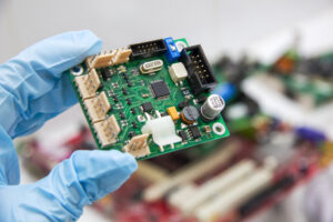
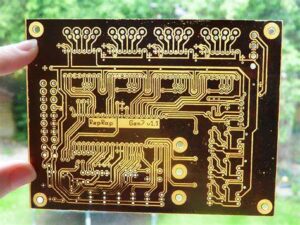
Reverse engineering PCB board requires a combination of hardware and software tools. Here’s a detailed list of the essential tools you’ll need:

Reverse engineering PCB board requires a combination of hardware and software tools
Hardware Tools for reverse engineering PCB board
- Multimeter
- For measuring voltage, resistance, and continuity of the circuit.
- Oscilloscope
- For analyzing signal waveforms and debugging electronic circuits.
- Soldering Iron
- Desoldering Pump (Solder Sucker)
- For removing solder from the PCB during component removal.
- Hot Air Rework Station
- Tweezers and Precision Tools
- For handling small components and precise work.
- Screwdrivers and Pliers
- Magnifying Glass or Microscope
- For inspecting small components and fine details on the PCB.
- Digital Caliper
- Scanner or High-Resolution Camera
- For capturing detailed images of the PCB’s layout.

Hardware Tools for reverse engineering PCB board
Software Tools for reverse engineering PCB board
- PCB Design Software
- For recreating the schematic and PCB layout.
- Examples: KiCad, Eagle, Altium Designer, OrCAD.
- Schematic Capture Software
- For drawing the circuit schematics.
- Image Processing Software
- For enhancing and processing PCB images.
- Examples: Adobe Photoshop, GIMP.
- Gerber Viewer
- For viewing and analyzing Gerber files (standard PCB design file format).
- CAD Software
- For 3D modeling and visualization of the PCB and components.
- Examples: FreeCAD, SolidWorks.
- Component Library Software
- For creating or downloading component libraries used in PCB design software.
Additional Resources
- Component Datasheets
- For understanding the specifications and pinouts of components used on the PCB.
- Circuit Simulation Software
- For simulating the circuit’s behavior and verifying the design.
- Examples: LTspice, PSpice.
- Documentation and Reference Materials
- For keeping detailed records of the reverse engineering process.
Optional Tools of reverse engineering PCB board
- X-ray Inspection System
- For inspecting inner layers of multilayer PCBs and hidden solder joints.
- Logic Analyzer
- For capturing and analyzing digital signals in complex circuits.
By using these tools, you can systematically reverse engineer a PCB to understand its design and functionality.


