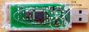
Relayout Electronic Circuit Board Anti-ESD Schematic Design should consider the circuitry layout of the I/O circuit which should be as close as possible to the corresponding connector, and circuits that are susceptible to ESD should be placed near the center of the circuit, so that other circuits can provide them with a certain shielding effect.

Relayout Electronic Circuit Board Anti-ESD Schematic Design should consider the circuitry layout of the I/O circuit which should be as close as possible to the corresponding connector, and circuits that are susceptible to ESD should be placed near the center of the circuit, so that other circuits can provide them with a certain shielding effect.
It is common to place resistors and magnetic beads in series at the receiving end. For those cable drivers that are easily hit by ESD, consider placing resistors or magnetic beads in series at the driving end.
Transient protectors are usually placed at the receiving end. Use a short and thick wire (length less than 5 times the width, preferably less than 3 times the width) to connect to the chassis ground. The signal and ground wires coming out of the connector must be directly connected to the transient protector before they can be connected to other parts of the circuit.
Filter capacitors should be placed at the connector or within 25mm from the receiving circuit.
(1) Use a short and thick wire to connect to the chassis ground or the receiving circuit ground (length is less than 5 times the width, preferably less than 3 times the width);
(2) The signal line and ground line are connected to the capacitor first and then to the receiving circuit.
Make sure the signal line is as short as possible, when the length of the signal line is greater than 300mm, a ground wire must be laid in parallel.
Make sure that the loop area between the signal line and the corresponding loop is as small as possible. For long signal lines, the position of the signal line and ground line must be changed every few centimeters to reduce the loop area.
Drive signals from the center of the network into multiple receiving circuits, ensure that the loop area between the power supply and ground is as small as possible, and place a high-frequency capacitor close to each power supply pin of the integrated circuit.


