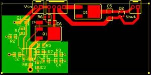
When we redraw Printed Circuit Board Ground Gerber Layer, the signal line crosses the gap between the two grounds. What is the return path of the signal current? Assume that the two grounds that are divided are connected together somewhere (usually in a certain position) single point connection, in this case, the ground current will form a large loop.

Redraw Printed Circuit Board Ground Gerber Layer is part of the process of printed circuit board reverse engineering through which can acquire schematic
The high-frequency current flowing through the large loop will produce radiation and high ground inductance. If the low-level analog current flows through the large loop, the current is easily interfered by external signals. The worst part is that when the split grounds are connected together at the power supply, a very large current loop will be formed. In addition, the analog ground and digital ground are connected together by a long wire to form a dipole antenna.
Understanding the path and method of current return to ground is the key to optimizing the PCB board design of mixed-signal circuit boards. Many design engineers only consider where the signal current flows, and ignore the specific path of the current. If the ground gerber layer must be divided, and must be routed through the gap between the divisions, you can first make a single point connection between the divided grounds to form a connection bridge between the two grounds, and then route through the connection bridge.


