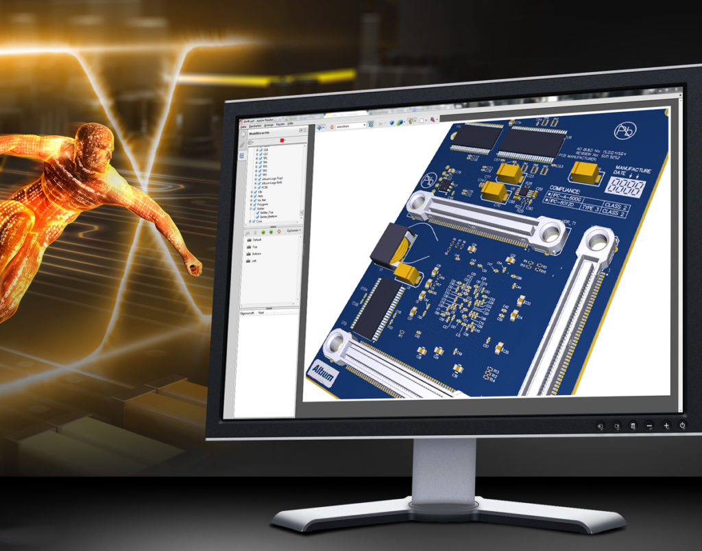
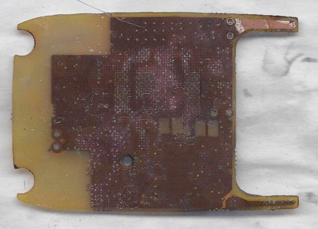
Redesign Data Acquisition System Circuit Board Layout can provide an effecitive way to Solve Grounding Issue, The grounding problem occupies a very important position in the anti-interference of the data collection system. It can be said that if the grounding problem is handled well, most of the interference problems in the data collection system are solved;

Generally, many types of ground wires will be designed on the printed circuit board, for example:
1, Signal ground (analog signal, digital signal and zero potential reference of signal source
2, Power ground (zero potential shielding ground of current network (also known as chassis ground) is designed to prevent electrostatic induction and electromagnetic induction;
3, AC ground (ground wire of AC 50Hz power supply
4, DC ground (the grounding of the DC power supply has proven that if the grounding of the data collection system is properly handled, it can suppress the coupling of internal noise to a large extent, prevent the intrusion of external interference, and improve the anti-interference ability of the system; otherwise, If the grounding is not handled properly, it will cause noise coupling and interference. Therefore, you should pay attention to the problem of grounding. Generally, when considering system grounding, the following grounding principles should be followed.

The principle of ground connection
Live conductors, including the earth, have electrical impedances. When current flows through them, potentials appear in the conductors. If the data acquisition system circuit board layout redesign is grounded at two points, the potentials around the earth are very different.
Consistent, therefore, it is difficult to ensure that the two separate ground points have equal potential, resulting in a certain potential difference between them, forming a loop current,
Thereby causing interference to the two-point circuit, then the ground potential difference is the main source of common mode interference at the input of the data acquisition system PCB board schematic diagram.
If the signal input terminal is grounded at a low frequency, common mode interference can be avoided.
It should be noted that for high-frequency circuits, one-point grounding method cannot be used, but multi-point grounding should be adopted.


