Radio Frequency PCB Circuitry Wiring Layout Reverse Engineering will try to make the RF trace 50 ohm impedance, if it is irrelevant, keep the width of the Radio Frequency PCB trace within 0.5mm~1mm, and keep the safety distance from the ground within 0.5mm~1mm, with ground holes around it. It is recommended that the radio frequency seat is as clear as possible, Via pads are recommended to end with teardrops.

Radio Frequency PCB Circuitry Wiring Layout Reverse Engineering
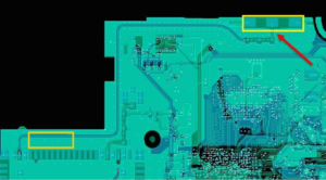
Radio Frequency circuit board traces should be as far away as possible from power supplies, SIM cards, clocks, and high-speed digital signals; ensure that they do not affect surrounding devices.
Therefore, it is recommended that customers do not place other components around the antenna and keep the traces on the PCB as far away as possible from the RF part.
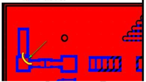
The Radio Frequency printed circuit board trace should be as short as possible, and a serpentine line or arc should be used when it is bent, and ground holes should be drilled around it.
When the RF trace is too long, it is recommended to reserve a matching circuit for module test and antenna test
If the board space is abundant, the priority is to achieve short and straight RF wiring through relayout electronic pcb card.

the priority is to achieve short and straight RF wiring through layout
.
Arc wiring should be used if it is really necessary. Right-angled, you can replace the traces by placing the components through the placement of the components to make a 90° angle turning, which can maximize the avoidance of signal reflection caused by sudden impedance changes.
If the board space is abundant, the priority is to achieve short and straight RF wiring through layout. If the layout space is not allowed, corner wiring is required, and right-angle or 45° corner wiring must be avoided. Arc wiring should be used if it is really necessary.

If the board space is abundant, the priority is to achieve short and straight RF wiring through layout.


