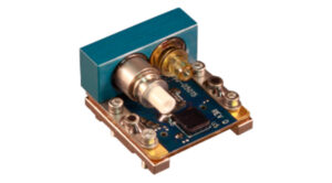
Photoelectric Signal Receiver PCB Board Reverse Engineering uses ANSYS simulation analysis software to perform random vibration simulation analysis on the Photoelectric Signal Receiver PCB Board during the conceptual design stage of the Photoelectric Signal Receiver electronic device.

Photoelectric Signal Receiver PCB Board Reverse Engineering
The focus is on the impact of random vibration on the reliability and optical coupling efficiency of Photoelectric Signal Receiver PCB Boards.
It is beneficial to improve the reliability of the product, verify the feasibility of the pcb board design, effectively avoid production waste, shorten the development cycle, and reduce the PCB board research and development cost.
1 The basic principle of random vibration response analysis Random vibration refers to a kind of vibration that cannot describe the law of motion with a deterministic function, and must use probability and statistics to describe the important characteristics of the random process.
If a system excitation of a random process is input, the output response is also a random process. The basic dynamic finite element equation [6] is Mü+Cu ·+Ku=F,
(1) Where: M is the N×M mass matrix; C is the N×M damping matrix; K is the N×M stiffness matrix; F is the external excitation vector;
u, u·, ü are the position shift amount of the unit node,
Speed vector and acceleration vector.
To obtain the statistical characteristics of random excitation vibration,
First, perform frequency response and signal integrity analysis to obtain the frequency response function H(ω) of the structure, and then obtain the power spectral density of the response.
For single-point excitation, the output power spectral density Sy(ω) has the following correspondence with the input power spectral density Sx(ω)
Sy(ω)=|H(ω)| 2Sx(ω).
(2) For multiple incentives, if the incentives are independent of each other,
Then the total response power spectral density S(ω) of the system is equal to the sum of the response power spectral density caused by each excitation,
That is, S(ω)=∑Syi(ω)=∑ Hi(ω)2Sxi(ω). (3)


