The component placement stage of the PCB Board Layout Reverse Engineering process is both science and art, requiring strategic consideration of the main components available on the circuit board. Although this process can be challenging, the way you place your electronic components will determine how easy your circuit board is to be reverse engineering and manufacture and how it meets your original printed circuit board re-design requirements.

The component placement stage of the PCB Board Layout Reverse Engineering process is both science and art, requiring strategic consideration of the main components available on the circuit board
Although there is a general order for component placement, such as placing connectors, printed circuit board mounting devices, power circuits, precision circuits, and critical circuits in order, there are some specific guidelines to keep in mind, including:
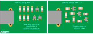
Orientation-Ensure that similar components are positioned in the same direction, which will help achieve an efficient and error-free welding process.

Orientation-Ensure that similar components are positioned in the same direction, which will help achieve an efficient and error-free welding process
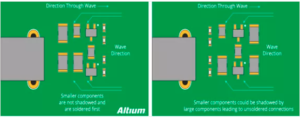
Arrangement-Avoid placing smaller components behind larger components, so that small components may be affected by the soldering of large components and cause mounting problems.

Arrangement-Avoid placing smaller components behind larger components, so that small components may be affected by the soldering of large components and cause mounting problems
It is recommended to place all surface mount (SMT) components on the same side of the PCB Board Layout Reverse Engineering, and place all through-hole (TH) components on the top of the circuit board to minimize assembly steps. One final PCB board layout design guideline to note-when using mixed technology components (through-hole and surface mount components), the manufacturer may require additional processes to assemble the circuit board, which will increase your overall cost


