Star Ground in PC Board Reverse Engineering
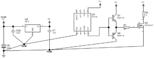
The Star Ground in PC Board Reverse Engineering philosophy builds on the theory that there is one single ground point in a circuit to which all voltages are referred. This is known as the star ground point. It can be better understood by a visual analogy—the multiple conductors extending radially from the common schematic ground resemble a star.
Note that the star point need not look like a star—it may be a point on a ground plane—but the key feature of the star ground system is that all voltages are measured with respect to a particular point in the ground network, not just to an undefined “ground” (i.e., wherever one can clip a probe).

star grounding in pc board reverse engineering
This star grounding philosophy is reasonable theoretically, but is difficult to implement practically. For example, if we design a star ground system through PC board reverse engineering, drawing out all signal paths to minimize signal interaction and the effects of high impedance signal or ground paths,
we often find implementation problems.
When the power supplies are added to the circuit diagram, they either add unwanted ground paths, or their supply currents flowing in the existing ground paths are sufficiently so large, or noisy (or both) so as to corrupt the signal transmission. This particular problem can often be avoided by having separate power supplies (and thus separate ground returns) for the various circuit portions.
For example, separate analog and digital supplies with separate analog and digital grounds, joined at the star point, are common in mixed signal applications.


