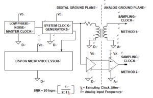
Ideally, the crystal oscillator used on Sampling Clock Distribution from ON Board Diagnotis PCB Cloning should be referenced to the analog ground plane in a split-ground system. However, this is not always possible because of system constraints. In many cases, the sampling clock must be derived from a higher frequency multipurpose system clock which is generated on the digital ground plane.
It must then pass from its origin on the digital ground plane to the ADC on the analog ground plane. Ground noise between the two planes adds directly to the clock signal and will produce excess jitter. The jitter can cause degradation in the signal-to-noise ratio and also produce unwanted harmonics.
This can be remedied somewhat by transmitting the sampling clock signal as a differential signal using either a small RF transformer as shown in below Figure or a high speed differential driver and receiver IC.

Sampling Clock Distribution from ON Board diagnotis PCB Cloning
If an active differential driver and receiver are used, they should be ECL to minimize phase jitter. In a single +5 V supply system, ECL logic can be connected between ground and +5 V (PECL), and the outputs ac coupled into the ADC sampling clock input. In either case, the original master system clock must be generated from a low phase noise crystal oscillator.


