Mutual Inductance in Diesel Power Module PCB Card Design
Another consideration regarding Mutual Inductance in Diesel Power Module PCB Card Design is the separation of outward and return currents. As we shall discuss in more detail later, Kirchoff’s Law tells us that current flows in closed paths—there is always an outward and return path. The whole path forms a single turn inductor.
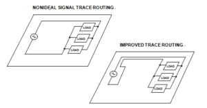
This principle is illustrated by the contrasting signal trace routing arrangements. If the area enclosed within the turn is relatively large, as in the upper “nonideal” picture, then the inductance (and hence the ac impedance) will also be large. On the other hand, if the outward and return paths are closer together, as in the lower “improved” picture, the inductance will be much smaller.
Note that the nonideal signal routing case of below Figure has other drawbacks—the large area enclosed within the conductors produces extensive external magnetic fields, which may interact with other circuits, causing unwanted coupling. Similarly, the large area is more vulnerable to interaction with external magnetic fields, which can induce unwanted signals in the loop.

Nonideal and Improved Signal Trace Routing
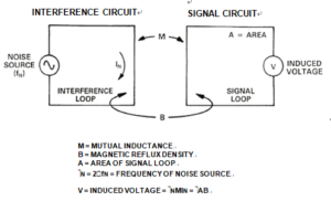
The basic principle is illustrated in below Figure, and is a common mechanism for the transfer of unwanted signals (noise) between two circuits PCB copying.

Basic Principles of Inductive Coupling


