Multilayer PC Board Impedance Design has been determined by PCB stack structure and it can redesign through reverse engineering printed circuit board schematic diagram and layout drawing;

Multilayer PC Board Impedance Design has been determined by PCB stack structure and it can redesign through reverse engineering printed circuit board schematic diagram and layout drawing;
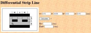
Common signal impedance types include single-ended 50 ohms, differential 100 ohms, single-ended radio frequency 50 ohms, etc. The impedance parameters can be calculated through the software Si9000.

Common signal impedance types include single-ended 50 ohms, differential 100 ohms, single-ended radio frequency 50 ohms
One point that needs to be mentioned in particular is the 50 ohm impedance control of single-ended radio frequency circuit board lines. Radio frequency PC board lines reverse engineering generally run on the surface (the purpose is to directly lead out without perforating to reduce the possibility of discontinuous impedance changes, and the surface signal speed is fast), And in order to enhance the anti-interference ability and reduce the loss, compared with ordinary signals, the RF line needs a thicker line width, generally at least 15mil.


