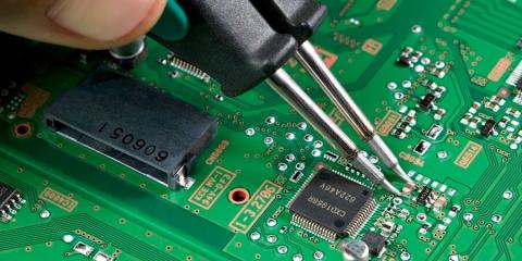
Malfunctional Canon SCH/EL PCB Board Troubleshooting can take advantage of analog signal analysis method, and there are several main points need to take into account for the process:

(1) Accumulate and improve VI curve library. The VI curves of various circuit board nodes that may be tested in the future are collected into a VI curve library as a reference standard for future fault detection, so that the detection capability and efficiency of the ASA test can be greatly improved.
(2) Master the basic VI curve. The basic VI curve refers to the VI curve of each pin when the components are offline (not soldered to the circuit board). Because the VI curve of the circuit node is actually a parallel curve of the basic curve associated with this node (that is, the slope of the red line at the node at a point is equal to the slope of the tangent line of each basic configuration line connected to this node Sum).
So if you know which components are associated with the node, you can often infer the approximate shape of the node curve;
Conversely, from the shape of the curve of the node, the type of the component associated with the node can be roughly inferred or when the node curve is abnormal, it can be inferred which component associated with it is most likely to fail.
The “curve” of the VI reflects the impedance characteristics at the junction. The shape of the curve in the actual circuit is diverse. We must be familiar with the curve shape of typical components, such as pure resistance force online, which has a large slope, and the pure capacitance of the resistance is an ellipse The larger the YX axis ratio, the larger the capacity.
And our common asymmetrical non-linear PN junction characteristic curves of diodes, voltage regulators and so on. The VI curve extracted in the actual circuit must be a synthesis of these typical curves.
Therefore, based on the geometry of the VI curve of the actual circuit node, you can roughly guess which components the node is composed of; on the contrary, you can also guess the approximate shape of the curve extracted by some attribute nodes. If it is far from the predicted shape, there must be a problem.
(3) Use a repeating circuit on the circuit board.
Repeated occurrences of subcircuits on some PCB boards can be used as a cross-reference. Through the VI curve test function in the PCB board maintenance tester, you can scan the device ports on the circuit board and pass the good and bad board control test to find the fault soon.
Sometimes when we can’t find a well functional PCB board for comparison database, we can use the same two Malfunctional Canon SCH/EL PCB Boards for test comparison. Because two damaged circuit boards are unlikely to be damaged at the same time in one place, the failure point can also be quickly found by handheld inspection terminals.


