
Cloning a PCB board has never been easier, thanks to the powerful combination of Autodesk Fusion 360 and Eagle. These two tools enable you to replicate, modify, or reverse engineer existing printed circuit boards (PCBs) with precision and ease.
অটোডেস্ক ফিউশন ৩৬০ এবং ঈগলের শক্তিশালী সংমিশ্রণের জন্য পিসিবি বোর্ড ক্লোন করা কখনও সহজ ছিল না। এই দুটি টুল আপনাকে বিদ্যমান প্রিন্টেড সার্কিট বোর্ড (পিসিবি)গুলিকে নির্ভুলতা এবং সহজে প্রতিলিপি, পরিবর্তন বা বিপরীত প্রকৌশলী করতে সক্ষম করে।
Step 1: Scan the Existing PCB Board
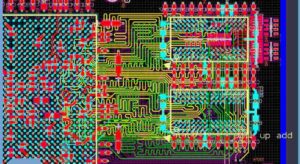
To start cloning a PCB board, you’ll need to create a digital representation of the original board. Use Eagle to generate the Gerber files, including the layout drawing, schematic diagram, and other essential data. These files serve as the foundation for creating a replica.
Чтобы начать клонирование печатной платы, вам нужно создать цифровое представление исходной платы. Используйте Eagle для генерации файлов Gerber, включая чертеж компоновки, принципиальную схему и другие важные данные. Эти файлы служат основой для создания реплики.
Step 2: Reverse Engineer with Eagle
Eagle allows you to extract the necessary files—such as the BOM list, netlist, and schematic diagrams—from the original board. This step is crucial for duplicating the PCB accurately. You can modify or restore any damaged components during this phase.
Step 3: Refine and Modify in Autodesk Fusion 360
Once the basic layout is complete in Eagle, use Fusion 360 to refine the design. Fusion 360’s advanced CAD tools help you adjust the layout and ensure optimal signal integrity and power distribution before generating the final Gerber data for manufacturing your cloned PCB board.
Eagle به شما این امکان را می دهد که فایل های لازم مانند لیست BOM، netlist و نمودارهای شماتیک را از برد اصلی استخراج کنید. این مرحله برای کپی برداری دقیق PCB بسیار مهم است. در این مرحله میتوانید اجزای آسیبدیده را اصلاح یا بازیابی کنید.
هنگامی که طرح اولیه در Eagle کامل شد، از Fusion 360 برای اصلاح طرح استفاده کنید. ابزارهای پیشرفته CAD Fusion 360 به شما کمک می کند تا طرح را تنظیم کنید و از یکپارچگی سیگنال و توزیع برق بهینه قبل از تولید داده های Gerber نهایی برای ساخت برد PCB شبیه سازی شده خود اطمینان حاصل کنید.
By using Autodesk Fusion 360 with Eagle, you can efficiently clone, reproduce, or modify any PCB board with precision.
Autodesk Fusion 360 with Eagle provides a powerful combination for PCB design and PCB reverse engineering services.
Here’s a step-by-step guide to using these tools for cloning a PCB board:
Step 1: Preparation
- Disassemble the PCB: Carefully remove any components from the PCB using a desoldering station. Note down the placement and orientation of each component.
- Document the PCB: Take high-resolution photos of both sides of the PCB. Ensure all traces and component labels are visible.
Step 2: Importing into Eagle
- Open Autodesk Eagle: If you don’t have it installed, download and install Autodesk Eagle from the Autodesk website.
- Create a New Project: Go to File > New > Project. Name your project and create it.
- Start a New Schematic: Right-click on the project and select New > Schematic.
- Create a Board Layout: Right-click on the project again and select New > Board.

How to use Autodesk Fusion 360 with Eagle to Clone PCB Board
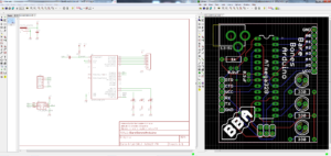
Step 3: Reconstructing the Schematic
- Add Components: Use the Add tool to place components on your schematic. Refer to your photos and notes to place the components accurately.
- Connect Components: Use the Net tool to draw connections between components based on the PCB traces you documented. This will create the schematic diagram.
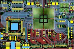
Step 4: PCB Layout Design Cloning
- Switch to Board Layout: Once the schematic is complete, switch to the board layout view by clicking the Generate/Switch to Board icon.
- Arrange Components: Place the components on the board layout according to their positions on the original PCB.
- Route Traces: Use the Route tool to draw the PCB traces, replicating the paths from the original PCB. Pay attention to the layer assignments (top, bottom, etc.) if it’s a multi-layer PCB.
Step 5: Integrate with Fusion 360
- Export from Eagle: Once your PCB board layout is complete, export it in a format that Fusion 360 can read. Go to File > Export and choose the appropriate format (e.g., DXF for the board outline).
- Open Fusion 360: If you don’t have it installed, download and install Autodesk Fusion 360 from the Autodesk website.
- Import into Fusion 360: Open Fusion 360 and import the file exported from Eagle. Go to File > Open and select the file.
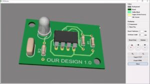
- Integrate Mechanical Design: Use Fusion 360’s powerful mechanical design tools to integrate the PCB into your overall product design. You can simulate the physical placement, check for fit, and make any necessary adjustments.
PCB layout design cloning by using Autodesk Fusion 360 with Eagle
Step 6: Verify and Test
- Check for Errors: Use the design rule check (DRC) in Eagle to ensure there are no errors in your pcb board layout cloning.
- Generate Gerber Files: If everything is correct, generate the Gerber files for manufacturing. Go to File > CAM Processor, and use the CAM job to create Gerber files.
- Manufacture and Assemble: Send the Gerber files to a PCB manufacturer. Once the PCBs are produced, assemble the components and test the board to ensure it functions correctly.
Additional Tips:
- Use Layers: Pay attention to different layers (e.g., top, bottom, inner layers for multi-layer PCBs) when routing traces in Eagle.
- Component Libraries: Make use of component libraries in Eagle for accurate component placement.
- Keep Detailed Notes: Document each step thoroughly, especially if you plan to make modifications or troubleshoot issues later.
By following these steps, you can effectively reverse engineer a PCB board using Autodesk Fusion 360 with Eagle. This combination of tools allows you to recreate the electronic and mechanical aspects of the board, ensuring a comprehensive and accurate reverse engineering process.


