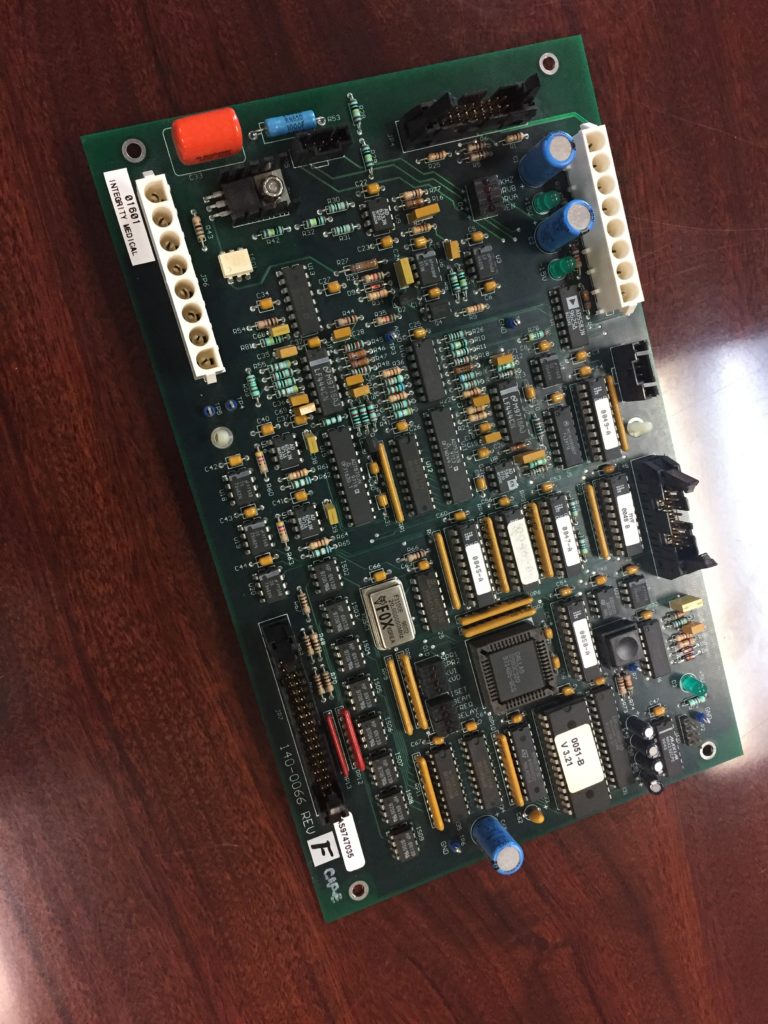
HITACHI OASIS MRI Mainboard Repairing will inspect the power supply system to the mainboard which could probably have greater possibility of failure since there are 6 modules will be applied.

The A+/A- ports of the six power modules are disconnected from the circuit and then turned on to measure the resistance of the A+ / A- ports. It is found that the resistance of the A+ / A- ports of the No. 2 power module is 3. 2Ω,
Prove that A+ / A- port is the signal output terminal when the power module outputs normal working voltage, That is: when the power module normally outputs 48V, A+ / A- the output voltage of the port is 0V, and when the power module has no output voltage, this port should output 5V, so that the computer system of the machine can detect the working status of the power supply board module, therefore, according to the working principle of the pull-down resistor, it is determined that the power supply module No. 2 can normally output voltage during operation, but the A+ / A- port does not pull the high level of 5V to the low level of 0V.
Therefore, the computer detected that the No. 2 power module was not working, which caused the machine to report an error and stopped the MRI controller card unit from starting troubleshotting.
Further analysis shows that, in fact, A+ / A- port is a normally open contact of a relay. It is closed when the power module is working and disconnected to output the working status of the power module when it fails. The relay contact inside the No. 2 power module When the power module is not working, it does not output a normal feedback signal to the control system.
Therefore, the system computer reported that the power supply of the gradient amplifier was faulty. Troubleshooting medical equipment circuit board: Short the A+ / A- port of the faulty power supply module No.2 directly, so that the computer system cannot detect the wrong feedback information, so that the MRI unit can start normally and the machine returns to normal.
Summary: Repairing this kind of equipment without schematic diagram which can be acuqired by reverse engineering printed wiring board, making full use of the fault code and indicator status, and measuring the voltage of each port are good methods. At the same time, the normal unit and the faulty unit are cross-exchanged to determine the fault.


