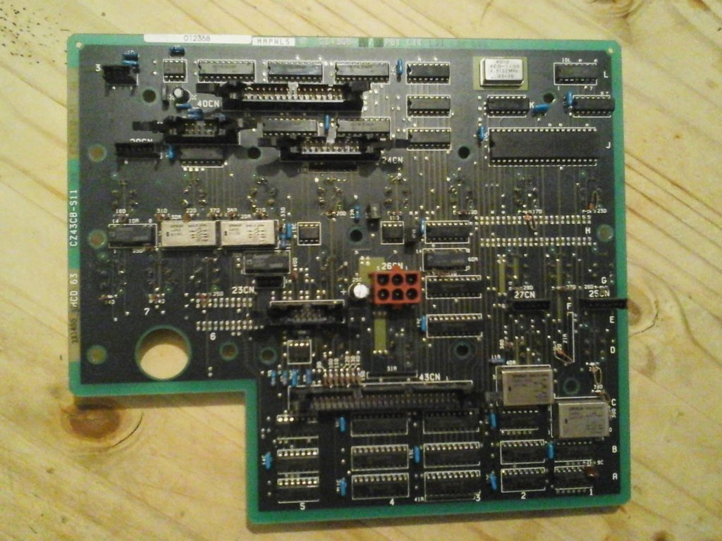
HITACHI Magnetic Resonance Imaging Controller Card Troubleshooting starts from circuit board repairing without schematic diagram and the Symptom of HITACHI Magnetic Resonance Imaging malfunctions is : “MR unit error” is reported when the machine starts. The machine does not start normally.

Fault check: First check the gradient amplifier of the MRI electronic card unit according to the error code, first open the cabinet and observe the status of the gradient amplifier: the signal lights of the three gradient amplifiers are only the normal status indicator of the z-axis amplifier is red, and the fault indicator 1 is red Defective Z-axis unit of the gradient amplifier.
Then use the keypad to enter the software system to view the error message, showing that the power supply to the gradient amplifier is wrong. The focus of the inspection is therefore on the power supply circuit board of the gradient amplifier.
Because the absence of electronic pcb card circuitry diagram of the MRI machine which can be extracted by PCB reverse engineering, first observe that each power indicator on the six power modules of the GP unit is green to indicate that the power module is working normally.
Then measure the output voltages of the six power modules one by one at 48V. At the same time, the total output DC voltage of the six power modules after series output is 287V is normal! Subsequently, the control board of the gradient amplifier was replaced with a channel displaying faulty and a channel displaying in the normal state. As a result, the fault phenomenon did not change, which proved that the gradient control board was normal.
Finally, in the power-on state, measure each A+ / A- terminal output end of the power supply of the GP unit one by one. It is found that the voltage of the A+ / A- terminal output of No. 2 power supply is 5V and the voltages of the other A+ / A- terminals are 0V. It is determined that there is a problem with the No. 2 power module. After the power is cut off, the resistance value of the A + A - terminal of each power module is infinite (in an open state). Prove that A+ / A- the port is in a normal state when no power is applied.


