In the High Speed Electronic Circuit Board Schematic Cloning, the power supply and the ground should be as close together as possible, and no PCB board re-wiring layout should be arranged in the middle.

High Speed Electronic Circuit Board Schematic Cloning, the power supply and the ground should be as close together as possible, and no PCB board re-wiring layout should be arranged in the middle
All wiring copper layers are as close as possible to a plane layer, and the ground plane is preferably a wiring isolation layer. In order to reduce the electromagnetic interference of signals between layers, the signal lines of adjacent wiring layers should be in a vertical direction.
You can reverse engineering 1-2 impedance control PCB layers according to your needs. If you need more impedance control layers, you need to negotiate with the PCB manufacturer.
The impedance control layer should be clearly marked as required. Distribute the network wiring required for impedance control on the board on the impedance control layer.
Setting of line width and line spacing.
Factors to be considered in the setting of line width and line spacing
A. The density of the veneer. The higher the density of the High Speed Electronic Circuit Board, the tendency to use finer line widths and narrower gaps.
B. The current intensity of the signal. When the average current of the signal is large, the current that the wiring width can carry should be considered.

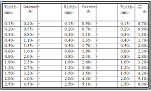
i. When copper is used as a wire to pass large currents, the current carrying capacity of the copper foil width should be derated by 50% with reference to the value in the table for selection consideration. ii. In PCB design and processing, OZ (ounces) is commonly used as the unit of copper thickness. 1 OZ copper thickness is defined as the weight of copper foil in 1 square foot area is one ounce, and the corresponding physical thickness is 35um; 2OZ copper thickness 70um
i. When copper is used as a wire to pass large currents, the current carrying capacity of the copper foil width should be derated by 50% with reference to the value in the table for selection consideration. ii. In PCB design and processing, OZ (ounces) is commonly used as the unit of copper thickness. 1 OZ copper thickness is defined as the weight of copper foil in 1 square foot area is one ounce, and the corresponding physical thickness is 35um; 2OZ copper thickness 70um


