High Speed DSP Interconnection on PCB Copy
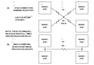
Below Figure shows a situation where several high speed DSPs must connect to a single point on PCB Copy, as would be the case when using read or write strobes bidirectionally connected from several DSPs. Small damping resistors shown in Figure A can minimize ringing provided the length of separation is less than about 2 inches. This method will also increase rise/fall times and propagation delay. If two groups of processors must be connected, a single resistor between the pairs of processors as shown in Figure B can serve to damp out ringing.

Series Damping Resistors for High Speed DSP Interconnections
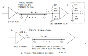
The only way to preserve 1 ns or less rise/fall times over distances greater than about 2 inches without ringing is to use transmission line techniques. Figure 12.42 shows two popular methods of termination: end termination and source termination. The end termination method (Figure A) terminates the cable at its terminating point in the characteristic impedance of the microstrip transmission line.
Although higher impedances can be used, 50 Ù is popular because it minimizes the effects of the termination impedance mismatch due to the input capacitance of the terminating gate (usually 5 pF to 10 pF).
In below Figure A, the cable is terminated in a Thevenin impedance of 50 Ù terminated to +1.4 V (the midpoint of the input logic threshold of 0.8 V and 2.0 V). This requires two resistors (91 Ù and 120 Ù), which add about 50 mW to the total quiescent power dissipation to the circuit.
Below Figure A also shows the resistor values for terminating with a +5 V supply (68 Ù and 180 Ù). Note that 3.3-V logic is much more desirable in line driver applications because of its symmetrical voltage swing, faster speed, and lower power. Drivers are available with less than 0.5 ns time skew, source, and sink current capability greater than 25 mA, and rise/fall times of about 1 ns. Switching noise generated by 3.3 V logic is generally less than 5 V logic because of the reduced signal swings and lower transient currents.

Termination Techniques for Controlled impedance Microstrip Transmission Lines


