The “ground plane” layer obtained from High Frequency PCB Board Cloning is often advocated as the best return for power and signal currents, while providing a reference node for converters, references, and other subcircuits. However, even extensive use of a ground plane does not ensure a high quality ground reference for an ac circuit.
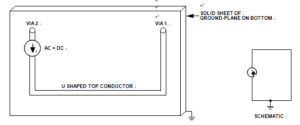
The simple circuit of below Figure, built on a two layer printed circuit board, has an ac and dc current source on the top layer connected to a via (via 1) at one end and to a single U-shaped copper trace connected to via 2. Both vias go through the circuit board and connect to the ground plane. Ideally, the impedance is zero and the voltage appearing across the current source is also zero.

Schematic and Layout of Current Source with U-shaped Trace on High Frequency PCB Board Cloning
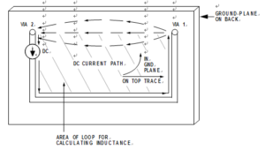
This simple schematic hardly begins to show the actual subtleties. But an understanding of how the current flows in the ground plane from via 1 to via 2 makes the realities apparent and shows how ground noise in high frequency layouts can be avoided.

The dc current flows in the manner in above Figure, as one might surmise, taking the path of least resistance from via 1 to via 2. Some current spreading occurs, but little current flows a substantial distance from this path. In contrast, the ac current does not take the path of least resistance, it take the path of least impedance, which, in turn, depends on inductance.


