Grounded Guard Trace on Fuel Ignition Controller PCB Layout
For the left-side inverting mode, note that the Pin 3 connected and Grounded Guard Trace on Fuel Ignition Controller PCB Layout surround the op-amp inverting input (Pin 2), and run parallel to the input trace. This guard would be continued out to and around the source and feedback connections of below Figure (or other similar circuit), including an input pad in the case of a cable. In the right-side noninverting mode, the guard voltage is the feedback divider voltage to Pin 2.

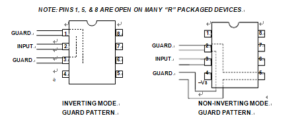
PCB Guard Patterns for Inverting and Noninverting Mode Op Amps Using Eight Pin SOIC (R) Package
This corresponds to the inverting input node of the amplifier, from below Figure. Note that in both of the cases of Figure 12.15, the guard physical connections shown are only partial—an actual layout would include all sensitive nodes within the circuit. In both the inverting and the noninverting modes using the MINI-DIP or other through hole style package, the PCB guard traces should be located on both sides of the board, with top and bottom traces connected with several vias.
Things become slightly more complicated when using guarding techniques with the SOIC surface mount (“R”) package, as the 0.05″ pin spacing doesn’t easily allow routing of PCB traces between the pins. But, there is still an effective guarding answer, at least for the inverting case. above Figure shows guards for the ADI “R” style SOIC package.
Note that for many single op amp devices in this SOIC “R” package, Pins 1, 5, and 8 are “no connect” pins. Historically these pins were used for offset adjustment and/or frequency compensation. These functions rarely are used in modern op amps. For such instances, this means that these empty locations can be employed in the layout to route guard traces. In the case of the inverting mode (left), the guarding is still completely effective, with the dummy Pin 1 and Pin 3 serving as the grounded guard trace.
This is a fully effective guard without compromise. Also, with SOIC op amps, much of the circuitry around the device will not use through hole components. So, the guard ring may only be necessary on the op amp PCB side.


