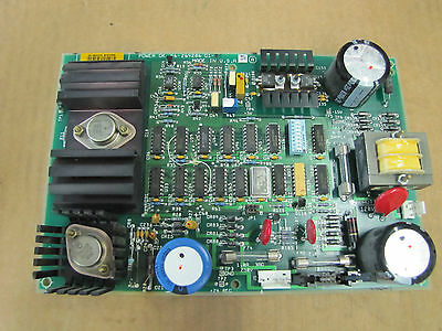
General Electric Power Supply Circuit Board Maintenance starts from appearance observation which will help us find out a obvious issue over the board:

The first step is to observe whether General Electric Power Supply Circuit Board has been artificially damaged, mainly in the following aspects:
① Whether the circuit board has been dropped, which has caused deformation of the corners of the board, or the chip on the board has been deformed or broken.
② Observe the socket of the chip to see if it is forcibly broken because there is no special tool.
③ Observe the integrated circuits on the circuit board. If it has a socket, first observe whether the chip is inserted incorrectly.
④ If there are short-circuit terminals on the circuit board, observe whether the short-circuit terminals are inserted incorrectly.
The second step is to observe whether the components on the circuit board are burned out. Under normal circumstances, even if the resistance is burned, its resistance value will not change, its performance will not change, and normal use will not be affected. At this time, a multimeter is needed to assist the measurement. However, if the capacitors and diodes are burned, their performance will change, and they can’t play their due role in the circuitry system, which will affect the normal operation of the entire General Electric Power Supply Circuit Board. At this time, new components must be replaced.
The third step is to observe whether the integrated circuit on the circuit board is bulging, MCU cracking, burning, or blackening. If this happens, it can basically be determined that the chip include mosfet, power delivery IC, signal transmission IC and other functional ICs has been burned out and must be replaced.
The fourth step is to observe whether the traces on the circuit board are peeling or burning. Is the sink hole removed from the pad? if there is any broken copper wire has been spotted over the board, by using the PC board layout drawing or schematic diagram will help us to figure out the connected functional block over the PCB Board which can facilitate the power board fixing process;
Step 5: Observe the fuse on the printed circuit board (including the fuse and thermistor) to see if the fuse is blown.


