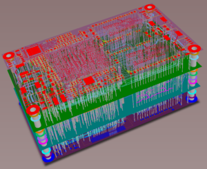
Fuel Cut Defencer PCB Board Reverse Engineeirng
Related to the star ground system discussed earlier is the use of a ground plane on Fuel Cut Defencer PCB Board Reverse Engineeirng. To implement a ground plane, one side of a double-sided PCB (or one layer of a multilayer one) is made of continuous copper and used as ground. The theory behind this is that the large amount of metal will have as low a resistance as is possible.
It will, because of the large flattened conductor pattern, also have as low an inductance as possible. It then offers the best possible conduction, in terms of minimizing spurious ground difference voltages across the conducting plane. Note that ground plane concept can also be extended to include voltage planes. A voltage plane offers advantages similar to a ground plane, i.e., a very low impedance conductor, but is dedicated to a one (or more) of the system supply voltages. Thus a system can have more than one voltage plane, as well as a ground plane.

Fuel Cut Defencer PCB Board Reverse Engineeirng
While ground planes solve many ground impedance problems, it should still be understood they aren’t a panacea. Even a continuous sheet of copper foil has residual resistance and inductance, and in some circumstances, these can be enough to prevent proper circuit function.
Designers should be wary of injecting very high currents in a ground plane, as they can produce voltage drops that interfere with sensitive circuitry. The importance of maintaining a low impedance large area ground plane from Fuel Cut Defencer PCB Board Reverse Engineeirng is critical to all analog circuits today. The ground plane not only acts as a low impedance return path for decoupling high frequency currents (caused by fast digital logic) but also minimizes EMI/RFI emissions. Because of the shielding action of the ground plane, the circuit’s susceptibility to external EMI/RFI is also reduced.


