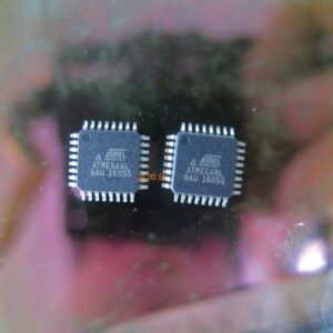
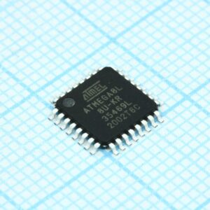
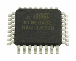
Reverse engineering atmel microcontroller atmega8l flash and eeprom memory to retrieve atmega8l mcu chip heximal file from its flash memory, after breaking off fuse bit of atmega8l avr microprocessor;

Reverse engineering atmel microcontroller atmega8l flash and eeprom memory to retrieve atmega8l mcu chip heximal file from its flash memory, after breaking off fuse bit of atmega8l avr microprocessor;
The INDF register is not a physical register. Addressing the INDF register will cause indirect addressing.
Indirect addressing is possible by using the INDF register. Any instruction using the INDF register actually accesses data pointed to by the File Select Register (FSR). Reading INDF itself indirectly will produce 00h. Writing to the INDF register indirectly results in a no operation to clone pci slot card printed circuit board (although Status bits may be affected). An effective 9-bit address is obtained by concatenating the 8-bit FSR register and the IRP bit (Status<7>), as shown in Figure 2-4.
The PIC16F688 has a wide variety of clock sources and selection features to allow it to be used in a wide range of applications while maximizing performance and minimizing power consumption. Figure 3-1 illustrates a block diagram of the atmega8l clock sources.

engenharia reversa ATMEL garantiu microcontrolador ATMEGA8L sistema de resistência a violação e extraiu o arquivo de programa de memória flash MCU bloqueado e o código-fonte de dados de memória eeprom para recuperar o firmware embutido do microprocessador ATMEGA8L criptografado de sua memória flash, depois de quebrar o bit de fusível do microprocessador AVR atmega8l;
Clock sources can be configured from external oscillators, quartz crystal resonators, ceramic resonators, and Resistor-Capacitor (RC) circuits. In addition, the system clock source can be configured from one of two internal oscillators in the process of copying printed circuit board, with a choice of speeds selectable via software. Additional clock features include:
Selectable system clock source between external or internal via
Two-Speed Clock Start-up mode, which mini- mizes latency between external oscillator start-up and code
Fail-Safe Clock Monitor (FSCM) designed to detect a failure of the external clock source (LP, XT, HS, EC or RC modes) and switch to the Internal
The atmega8l can be configured in one of eight clock modes.
-

ingeniería inversa ATMEL aseguró el microcontrolador ATMEGA8L el sistema de resistencia a la manipulación y extrajo el archivo de programa de memoria flash MCU bloqueado y el código fuente de datos de la memoria eeprom para recuperar el firmware integrado del microprocesador ATMEGA8L cifrado de su memoria flash, después de romper el bit de fusible del microprocesador ATMEGA8L AVR;
EC – External clock with I/O on
- LP – Low gain Crystal or Ceramic Resonator Oscillator
- XT – Medium gain Crystal or Ceramic Resona- tor Oscillator mode.
- HS – High gain Crystal or Ceramic Resonator
- RC – External Resistor-Capacitor (RC) with FOSC/4 output on
- RCIO – External Resistor-Capacitor with I/O on
- INTRC – Internal oscillator with FOSC/4 output on RA4 and I/O on
- INTRCIO – Internal oscillator with I/O on RA4 and RA5.
Clock source modes are configured by the FOSC<2:0> bits in the Configuration Word register (see Section 11.0 “Special Features Of The CPU”). The internal clock can be generated by two oscillators. The HFINTOSC is a high-frequency calibrated oscillator. The LFINTOSC is a low-frequency uncalibrated oscillator.


