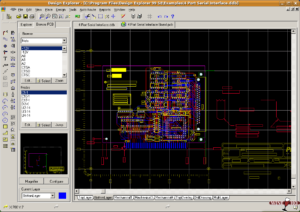
Electronic Circuit Board Gerber File Recreation can reduce unnecessary costs caused by fault inspection and rework which are becoming quite in the high speed and high interconnect/density PCB layout design.
In the original PCB design, because the transient voltage suppressor (TVS) diode is used to suppress the direct charge injection caused by ESD discharge, it is more important in reverse engineering circuit board layout scheme to overcome the electromagnetic interference (EMI) electromagnetic field effect generated by the discharge current. Hereby we will provide PCB layout redesign guidelines that can optimize ESD protection.

Electronic Circuit Board Gerber File Recreation can reduce unnecessary costs caused by fault inspection and rework which are becoming quite in the high speed and high interconnect/density PCB layout design
The current enters the circuit loops by induction. These loops are closed and have varying magnetic flux. The amplitude of the current is proportional to the area of the loop. The larger loop contains more magnetic flux, so a stronger current is induced in the circuit.
Therefore, the loop area must be reduced. The most common loop is shown in Figure 1, formed by power and ground. When possible, multi-layer PCB designs with power and ground planes can be used.
The reason why we have to switch to multilayer circuit board design is because it is not only minimizes the loop area between the power supply and ground, but also reduces the high-frequency EMI electromagnetic field generated by the ESD pulse. If a multi-layer circuit board cannot be used, the wires for power and ground must be connected in a grid as shown in Figure 2.


