ADC Digital Output in ECU Board Reverse Engineering
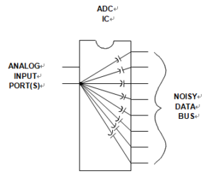
ADC Digital Output in ECU Board Reverse Engineering is important for the whole design process, as a result of that, it is always a good idea to place a buffer register adjacent to the converter to isolate the converter’s digital lines from noise on the data bus. The register also serves to minimize loading on the digital outputs of the converter and acts as a Faraday shield between the digital outputs and the data bus, See below Figure.
Even though many converters have three-state outputs/inputs, these registers are on the die and still allow the signals on the data pins to couple into sensitive areas. This isolation register still represents good design practice. In some cases it may be desirable to add an additional buffer register on the analog ground plane next to the converter output to provide greater isolation.

A High Speed ADC IC Using a Buffer at the Output Shows Enhanced Immunity to Digital Data Bus Noise applied in ecu board reverse engineering
The series resistors (labeled “R” in above Figure) between the ADC output and the buffer register input help to minimize the digital transient currents which may affect converter performance. The resistors isolate the digital output drivers from the capacitance of the buffer register inputs.
In addition, the RC network formed by the series resistor and the buffer register input capacitance acts as a lowpass filter to slow down the fast edges. A typical CMOS gate combined with PCB trace and a through hole will create a load of approximately 10 pF. A logic output slew rate of 1 V/ns will produce 10 mA of dynamic current if there is no isolation resistor:


