Microstrip Transmission Lines on Digital Racing Dash Display PCB Cloning
For a simple two-sided Digital Racing Dash Display PCB Cloning where one side is a ground plane, a signal trace on the other side can be designed for controlled impedance. This geometry is known as a surface microstrip, or more simply, microstrip.
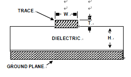
A cross-sectional view of a two-layer PCB illustrates this microstrip geometry as shown in below Figure.

A Microstrip Transmission Line with Defined Impedance Is Formed by a PCB Trace of Appropriate Geometry, Spaced from a Ground Plane
For a given PCB laminate and copper weight, note that all parameters will be predetermined except for W, the width of the signal trace. Eq. 1-1 can then be used to design a PCB trace to match the impedance required by the circuit. For the signal trace of width W and thickness T, separated by distance H from a ground (or power) plane by a PCB dielectric with dielectric constant εr, the characteristic impedance is:

equation 1-1
Note that in these expressions, measurements are in common dimensions (mils). These transmission lines will have not only a characteristic impedance, but also capacitance. This can be calculated in terms of pF/in as shown in Eq. 1-2.

equation 1-2


