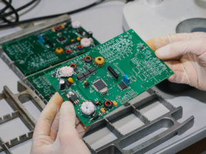
Dielectric Absorption on Aeromotive Electronics PCB Board Layout
Dielectric Absorption on Aeromotive Electronics PCB Board Layout most noticeably influences dynamic circuit response, for example, settling time. Unlike circuit leakage, the effects aren’t usually linked to humidity or other environmental conditions, but rather, are a function of the board’s dielectric properties.
The chemistry involved in producing plated through holes seems to exacerbate the problem. If your circuits don’t meet expected transient response specs, you should consider PCB dielectric absorption as a possible cause.

Dielectric Absorption on Aeromotive Electronics PCB Board Layout
Fortunately, there are solutions. As in the case of capacitor dielectric absorption, external components can be used to compensate for the effect. More importantly, surface guards that totally isolate sensitive nodes from parasitic coupling often eliminate the problem (note that these guards should be duplicated on both sides of the board, in cases of through hole components). As noted previously, low loss PCB dielectrics are also available.
PCB “hook,” similar if not identical to dielectric absorption, is characterized by variation in effective circuit board capacitance with frequency (see Reference 1). In general, it affects high impedance circuit transient response where board capacitance is an appreciable portion of the total in the circuit. Circuits operating at frequencies below 10 kHz are the most susceptible. As in circuit board dielectric absorption, the board’s chemical makeup very much influences its effects from PCB Reverse Engineering.


