In the process of DDR Memory Circuit Board Layout Design, the signals DQ, DM, and DQS are all point-to-point interconnections, so no topology is required for printed circuit board cloning. However, the exception is that this is not the case in the reverse engineering of multi-rank DIMMs (Dual In Line Memory Modules) design. In the point-to-point mode, impedance matching can be easily achieved through the impedance setting of the ODT, so as to achieve its waveform integrity.
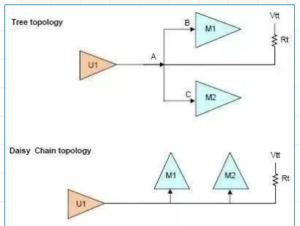
As for ADDR/CMD/CNTRL and some clock signals, they all need multi-point interconnection, so you need to choose a suitable topology. Below Figure lists some related topologies. Among them, the Fly-By topology is a kind of Special daisy chain, it does not need very long wires, and sometimes even short wires (Stub) are not needed. For DDR3, all these topologies are applicable, but the prerequisite is that the traces should be as short as possible.

The Fly-By topology has good waveform integrity in dealing with noise, but it is difficult to implement on a 4-layer PCB board, requiring more than 6 layers, while the daisy chain topology is easy to implement on a 4-layer circuit board cloning. In addition, the tree topology requires the length of AB to be very close to the length of AC.

DDR Memory Circuit Board Layout Design Reverse Engineering
Considering the integrity of the waveform and increasing the trace length of the branch as much as possible, while meeting the constraints of the board layer, in the multilayer-layer board-based DDR3 design reverse engineering, the most reasonable topology is to have the least short line (Stub ) Daisy chain topology.


