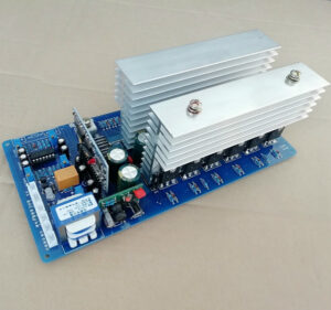
DC to AC Power Inverter PCB Board Cloning needs to pay attention to the design and layout over its digital and analog circuitry, clock and high speed schematic diagram schedule,
Digital and Analog
1. Whether the traces of the digital circuit and the analog circuit are separated in pcb card reverse engineering, and whether the signal flow is reasonable;
2. If the DC to AC Power Inverter PCB Board are divided into ground, whether the signal line between the circuits goes from the bridge point between the two grounds (except for the differential line)
3. Signal lines that must span the gap between split power supplies should be referenced to a complete ground plane;
4. If the cloned pcb circuit board ground layer design is not divided into partitions, make sure that the digital signals and analog signals are partitioned and routed.

DC to AC Power Inverter PCB Board Cloning
CLOCK and HIGH-SPEED section
1. Whether the impedance of each layer of the high-speed signal line is consistent
2. Whether the high-speed differential signal lines and similar signal lines are of equal length, symmetrical, and parallel to the nearest neighbor
3. Make sure the clock line goes as far as possible on the inner layer
4. Confirm whether the clock line, high-speed line, reset line and other strong radiation or sensitive lines have been routed according to the 3W principle as much as possible
5. Check whether there are no bifurcated test points on clock, interrupt, reset signal, 100M/Gigabit Ethernet, high-speed signal
6. Whether the low-level signal such as LVDS and the TTL/CMOS signal meet 10H as far as possible (H is the height of the signal line from the reference plane)
7. Whether the clock lines and high-speed signal lines avoid passing through dense through-hole via areas or routing between device pins
8. Whether the clock line has met the (SI constraint) requirements (whether the clock signal line has fewer holes, short lines, and continuous reference plane, the main reference plane should be GND as much as possible; if the GND main reference plane is changed when changing layers layer, it is a GND via within 200 mil from the via; if the main reference plane of different levels is changed when changing layers, is there a decoupling capacitor within 200 mil from the via) 9. Whether differential pairs, high-speed signal lines, and various types of BUS have met (SI constraints) requirements


